This is the first post in a series about how I implemented MQTT controller for a Heat Recovery Ventilator (HRV) in my house, and hooked it up to my home automation system.
What is HRV?
Our house is quite new, and therefore pretty well sealed. In order to maintain a healthy interior climate and not lose too much energy in a cold Canadian climate, we have a Heat Recovery Ventilator system, which is a system that brings in fresh outdoor air and heats (or cools) it with an interior air it exhausts, thus reducing energy costs.
This system is normally controlled by a humidistat/timer, which typically runs the fans 10-20 minutes every hour or so, and can control interior humidity somewhat (if the outdoor air is significantly drier than the indoor air).
The objective
My home automation system has multiple temperature and humidity sensors, indoors and outdoors and it knows about home occupancy. I plan to install CO2 and particulate matter sensors to monitor indoor air quality in the future. I’d like to use this data to control the HRV from Home Assistant, in a much smarter way than with a simple timer or humidistat.
Electronics
My HRV is Lifebreath RNC5-TPD. The communication protocol between the humidistat and the main unit is propitiatory, but it also supports “dumb” dry contact mode. The manual says:
- Low Speed: A jumper between 2 (ON) and 1 (LOW) initiates low speed ventilation.
- High Speed: A jumper between 2 (ON) and 6 (HI) initiates high speed ventilation.
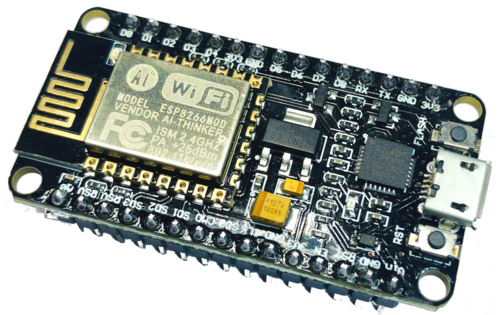
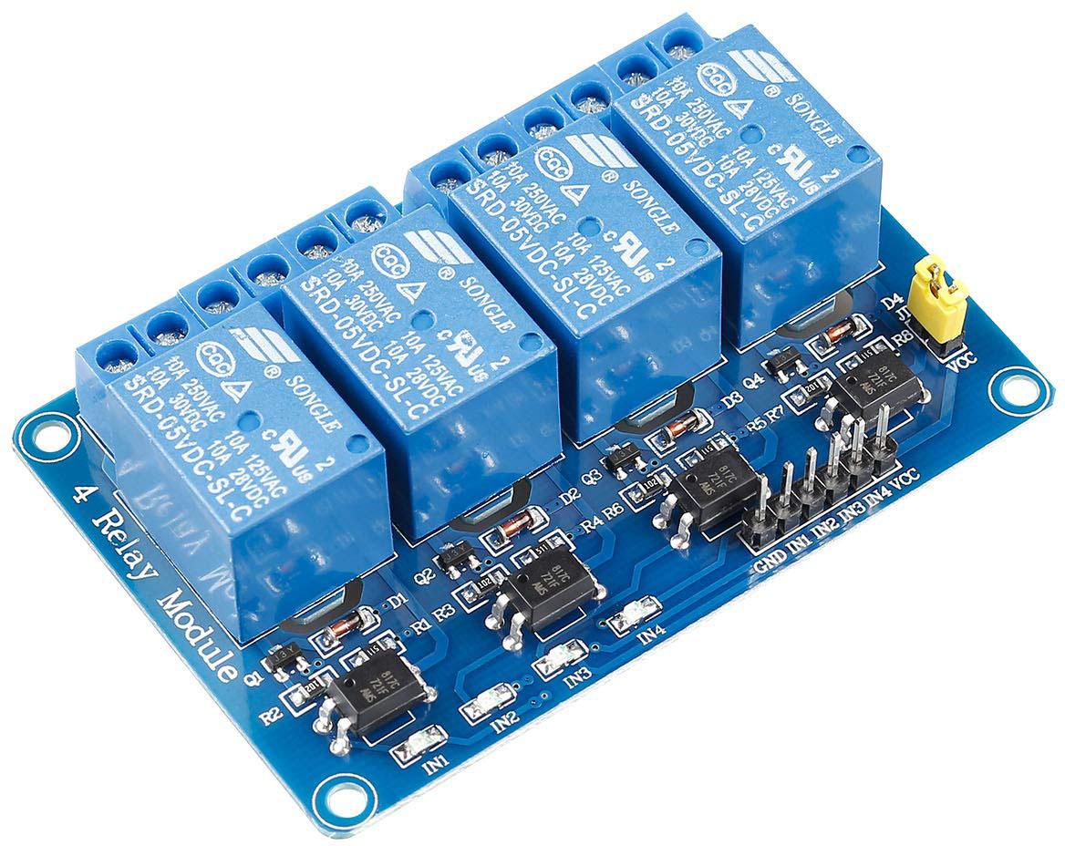
I decided to use a ESP8266-based Wi-Fi SOC board + a relay expansion board to control these contacts. The ESP8266 is an amazing little chip: it’s a microcontroller with a Wi-Fi interface, it has enough memory and CPU power to be useful, it’s very cheap, and is very simple to hook up.
I’ve got the ESP-12F board from Banggood.com (3 boards for $20!) and the 4 channel 5V relay board from Amazon ($10). In addition to that, I needed:
- A small project box to house everything.
- A button for local control in case the Home Automation system is down.
- A LED for a visual indication of a currently active operation mode.
- An old phone 5V power supply.
All these I had in my “random junk” bin.
Wiring it all together
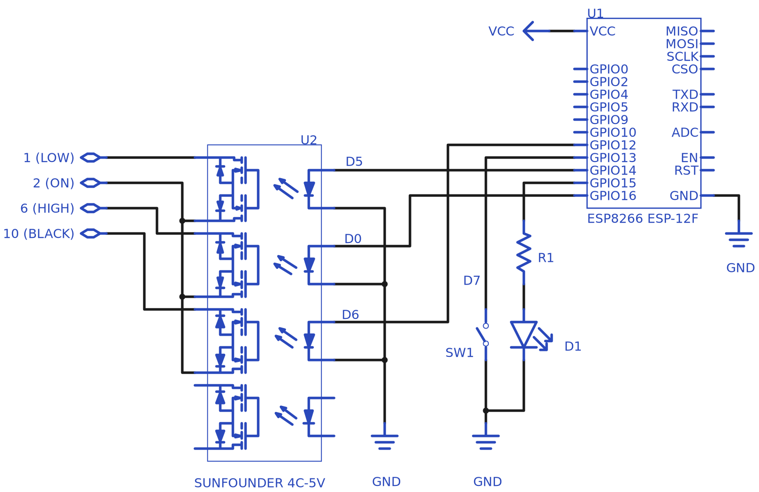
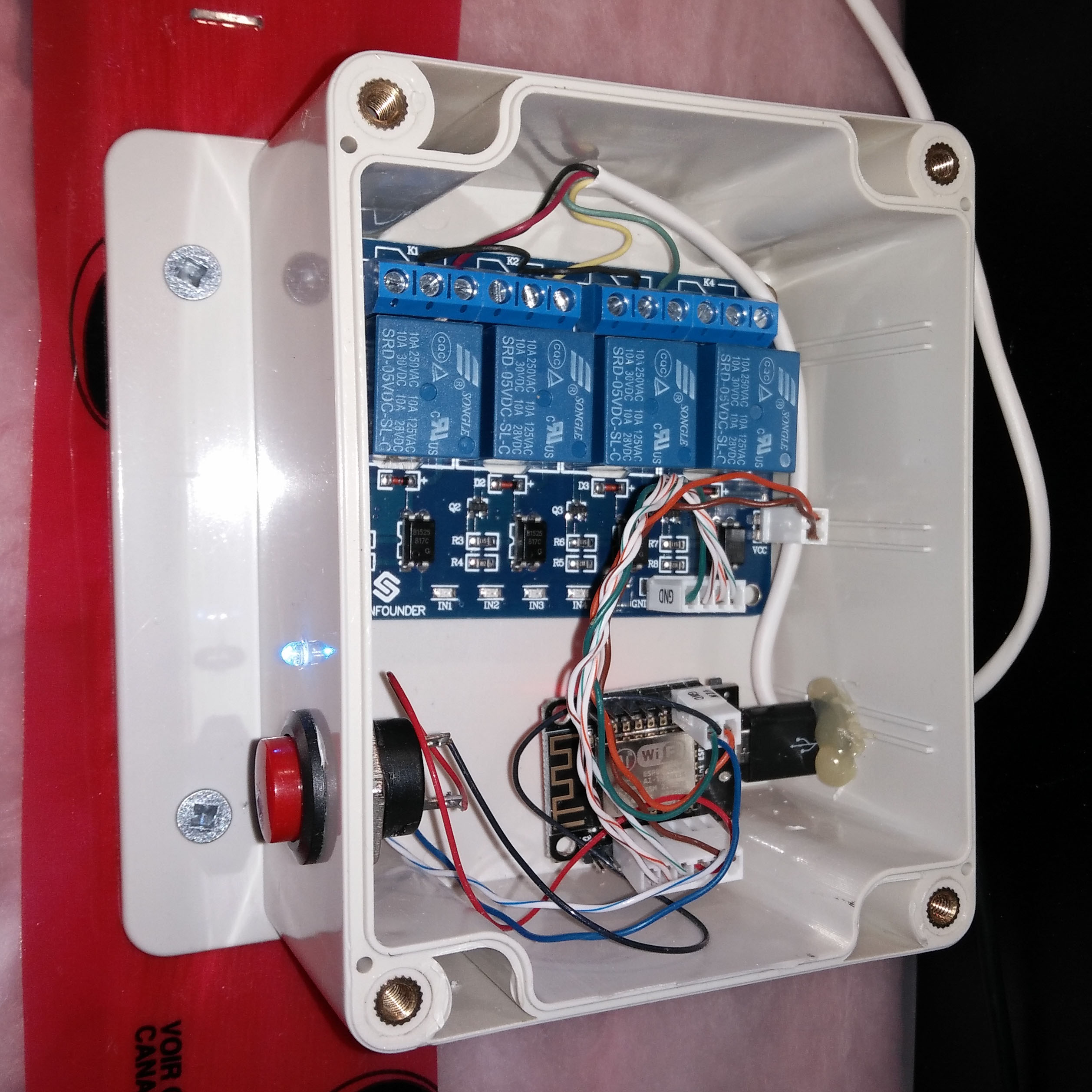
The circuit is trivial: a couple of GPIO pins control two relays, which control the “high” and “low” modes of the HRV, one GPIO pin is for the external indication LED, and one is for the local control button: Here is the circuit diagram and how it looks, mounted on a wall in my basement (I removed the box cover for demonstration purposes):
Next: software and firmware
In the next post, I’ll discuss the software needed to make it all work.